![<?echo $_SERVER['SERVER_NAME'];?>](/template/twentyseventeen/skin/images/header.jpg)
This article mainly introduces how the digital multimeter judges the electrolytic capacitor.
1) Good and bad judgment
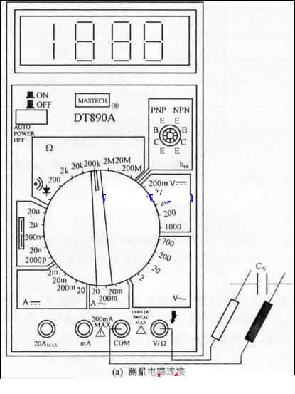
The first step: the choice of gear. Set the digital multimeter's switch to the gear marked with “Ω†and select the “diode with buzzer†range gear.
The second step: detection operation. Both pens are positive and negative, touching the two pins of the capacitor. At this time, immediately after the number displayed on the LCD screen flickers rapidly, the initial symbol (or "overflow symbol") "1" is displayed, and then the test leads are exchanged for another measurement. At this time, the number displayed on the LCD screen is preceded by a negative sign "~", and then the number rapidly flickers and the starting symbol "1" appears. The above situation shows that the positive and negative charging processes of the measured capacitor are normal and good. If the number displayed on the LCD screen during the above test process does not show "1" after rapid flicker, there will always be an unstable resistance reading indicating that the measured capacitor is leaking electricity; if two tests are exchanged The LCD displays “0†(or close to “0â€), and the buzzer sounds continuously, indicating that the measured capacitor is short-circuited; if only the overflow symbol “1†is displayed, there is no digital flicker process. Explain that the capacitor under test is open circuited.
Note: For a capacitor with a large capacity, when the two pens touch the pins at both ends of the capacitor, the buzzer will have a short pulsing process. The larger the capacity, the longer the buzzer will make a sound. This is because at the beginning of the charging of a large-capacity capacitor, there are a large number of dissimilar charges in the circuit that move and accumulate toward the two plates of the capacitor, resulting in a large current in the circuit and a low impedance. Therefore, when testing a capacitor with a large capacity, the time that the probes are in contact with the capacitor pins must not be too short, otherwise it will easily lead to erroneous judgments.
The third step is whether or not to detect leakage.
When the detection in the second step is completed and the digital flickering process on the LCD screen of the digital multimeter ends, and only the overflow symbol “1†is no longer changed, it indicates that the charging process of the tested capacitor ends, and both ends already have 2.6V. The left and right energy storage voltage (this voltage is the voltage between the two meter pens when the digital multimeter uses a diode block). At this time, the test lead is removed from the capacitor pin, and then the digital multimeter switch is set to the DC voltage measurement range marked "V-" symbol, select the 20V range gear, and then the two table pens are respectively in contact with the two capacitors Pin, detects the energy storage voltage across it. Observe the fast and slow rate of voltage drop on the LCD screen to determine whether the measured capacitor is leaking. If the voltage reading gradually decreases at an extremely slow rate, it is the capacitor's energy storage through the internal resistance. Released, indicating that the measured capacitor has no leakage phenomenon; if the voltage reading rapidly drops, it quickly drops to 0, indicating that the measured capacitor has a leakage phenomenon and cannot be used in the circuit.
2) Judgment on whether capacity changes
The first step is to use a soldering iron to lengthen the pins on both ends of the capacitor to facilitate insertion into the digital multimeter's capacitor measurement jack.
The second step: capacity detection operation. Set the switch of the digital multimeter to the capacitance measurement range marked with “F†and select an appropriate range according to the nominal capacity of the tested capacitor. The extended capacitor pins are then discharged by touching each other several times. After the discharging operation, the two pins are respectively inserted into two bar-shaped jacks marked with "cx". Because the two strip jacks have positive and negative points, when inserting capacitor pins, the positive and negative polarity of the electrolytic capacitor under test shall be respectively aligned with the “+†and “1†symbols marked on the jack. Insert to ensure measurement accuracy.
The third step: judge according to the reading.
When the reading displayed on the LCD screen is stabilized after a short time change, the quality of the capacitor can be judged based on the difference between the nominal capacity and the reading. Since the allowable error range of the helium and tantalum electrolytic capacitors is ±10%, if the displayed reading is stable within the allowable error range, the measured capacitor is good; if the reading is too small compared to the nominal capacity It shows that the capacity of the capacitor has changed and cannot be used. If the overflow symbol “1†does not change at the beginning of the LCD screen, it indicates that the internal circuit of the capacitor is damaged or the electrolyte is dry and has completely lost its capacity; The reading shows “0†or close to “0,†and the buzzer sounds all the time, indicating an internal short circuit in the measured capacitor.
Wooden Mop Stick,Pvc Coated Wooden Mop Stick,120Cm Wooden Mop Stick
Yeson International Trading Co., Ltd. , http://www.jssteelsheet.com