![<?echo $_SERVER['SERVER_NAME'];?>](/template/twentyseventeen/skin/images/header.jpg)
In general, in modern RF systems, the antenna receives a high frequency signal and has a very small channel bandwidth. If you consider directly filtering out the required channel, the Q value of the filter will be very large, and the high-frequency circuit has problems in terms of gain, accuracy, and stability. Under the current technical conditions, the signal is directly demodulated in the high frequency band. It is unrealistic. Using a mixer to down-convert high-frequency signals, channel filtering, amplification, and demodulation at an intermediate frequency can solve the above-mentioned difficulties encountered in high-frequency signal processing, but introduce another serious problem, that is, image frequency interference. : When the frequency difference between the frequency of the two signals and the local oscillator (LO) signal is symmetrically located on both sides of the local oscillator signal on the frequency axis, or their absolute values ​​are equal but the signs are opposite, then both signals are mixed after mixing Will be moved to the same IF frequency. If one of them is a useful signal and the other is a noise signal, the frequency at which the noise signal is located is called the image frequency. This mixed interference phenomenon is often called image interference. In order to suppress image interference, a commonly used method is to use a filter to filter out image frequency components. However, since the filter operates in the high frequency band, the filtering effect depends on the distance between the image frequency and the signal frequency, or on the frequency of the intermediate frequency. If the IF frequency is high and the signal frequency is far from the image frequency, the image frequency component is greatly suppressed. Conversely, if the IF frequency is lower, the signal frequency is not far from the image frequency, and the filtering effect is poor. On the other hand, since the channel selection is performed in the IF band, for the same reason, the higher IF frequency has higher requirements for the channel selection filter. Therefore, image frequency suppression and channel selection form a pair of contradictions, and the selection of the intermediate frequency becomes the key to balancing this contradiction. In some demanding applications, two or three conversions are often used to achieve a better compromise.
A well-designed superheterodyne receiver achieves high sensitivity, selectivity and dynamic range, thanks to thoughtful IF frequency selection and high quality RF (mirror rejection) and IF (channel selection) filters, which have long been Classic traditional choice. As mentioned earlier, superheterodyne receivers have a large advantage in suppressing image frequency interference, sensitivity and selectivity, and multi-level conversion has no DC drift and signal leakage, but also has high cost and high IR filter. The disadvantages of low noise amplifier (LNA) and mixer (Mixer) and good matching of 50W are required, and the image frequency suppression filter and channel selection filter are generally not suitable for monolithic integration.
Later zero-IF (Zero IF) structure, as shown in Figure 1, does not require a suppression filter, and the cross-modulation is reduced, which is more suitable for monolithic integration. However, there are also shortcomings of DC offset and signal leakage, and frequency synthesizers requiring high frequency and phase noise also bring certain difficulties to the circuit design. Similar to zero-IF, the low-IF (Low IF) structure is also suitable for integration. Its structure is shown in Figure 2 (both figures are based on the IEEE802.15.4 protocol in the 2.4 GHz band). However, it is necessary to pay attention to the suppression of the in-band image frequency signal. A 70dB image rejection ratio is usually required, but often the on-chip integration can only reach 40dB or less.
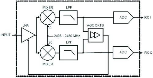
Figure 1 Zero IF receiver structure
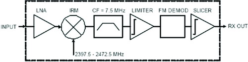
Figure 2 Low IF receiver structure
Other receiving structures include wideband-dual IF receivers, sampling receivers, and digital IF receivers. The broadband-dual IF receiver structure has the advantages of easy integration, low cost, low power consumption, etc., and its disadvantages are obvious influence of flicker noise and second-order intermodulation distortion, and there is a problem of radio frequency intermediate frequency crosstalk. Sub-sampling receivers and digital IF receivers have high requirements on analog-to-digital converters (ADCs), such as ADCs with high enough dynamic range, bandpass Σ-Δ ADCs, etc. The overnight-Δ ADC has a large design difficulty.
For the reasons mentioned above, the design of the current RF chip with zero-IF and low-IF schemes is more common, and it is also the two schemes that the RF receiver usually needs to carefully evaluate. The zero intermediate frequency uses IQ demodulation to extract the phase, quadrature component and other information, which is digitized and processed by the ADC. The low IF uses a typical frequency-limiting discriminator to extract the signal from the modulated carrier.
The low intermediate frequency structure avoids the automatic gain control (AGC) circuit and has a fast response speed to the channel signal, thereby reducing the complexity of the receiver and related circuits. The circuit such as the frequency discriminator is easy to design, does not require carrier synchronization and large current, and occupies a small chip area. However, compared to the zero-IF architecture with coherent demodulation, the sensitivity of the low-IF architecture is 3 dB. Moreover, usually the low IF structure requires a channel filter to obtain an effective carrier frequency, reducing the influence of noise, adjacent channel interference, and the like. If the signal frequency width defined by the protocol used by the RF system and the adjacent channel selection requirements are looser, the filter requirements are lower. The low IF architecture also requires an image rejection mixer to reduce image interference.
For low-chip protocol, such as 2M Chips/s, the modulation width is required to be approximately 2 MHz. If the intermediate frequency is too low and the relative bandwidth of the channel filter is too high, then the filter is difficult to implement, and it is difficult to filter out the IF signal, and the difficulty is passed on to the digital filter of the baseband. Conversely, an IF filter frequency that is too high requires the amplifier's bandwidth to be large enough.
Compared to the low IF, the zero-IF architecture does not require the local oscillator to change the frequency between the receive and radiate modes, which reduces the difficulty of the frequency synthesizer design. The zero-IF architecture also does not require an image rejection mixer because the zero-IF architecture does not produce an image frequency. Compared to the design of equal-bandwidth mid-band pass filters, the zero-IF architecture requires only a simpler low-pass filter to determine the I-to-Q-channel output signal-to-noise ratio. The zero-IF architecture allows for optimal demodulation on filter matching and synchronous detection techniques.
However, zero intermediate frequency has its own shortcomings compared to low intermediate frequency technology. For example, AGC, the DC offset cancellation circuit after the mixer is required, and since the signal is divided into two paths, I and Q, two analog-to-digital converters (ADCs) and a common ADC are required to simulate the signal. Number conversion. An IQ analog interface is required between the IQ two-way and the baseband chip or the integrated baseband circuit. An important design difficulty of the IQ structure is the IQ balance problem. The amplitude and phase imbalance between the two IQs will result in an IQ image superimposed on the wanted signal, which will degrade EVM performance. Therefore, the zero-IF architecture sometimes requires additional circuitry to isolate the baseband chip for simultaneous demodulation. Table 1 gives an area comparison of two designs for an IEEE 802.15.4 RF receiver in a 0.18 mm process.
Through the above description, the advantages and disadvantages of several common receiving structures are briefly compared. Choosing the architecture that best fits the protocol also includes considerations for power consumption, overall matching, image cancellation, flicker noise, and quality noise. In terms of low power consumption, there are direct conversion, SD ADC (Low pass SD ADC), and Quadrature band pass SD ADC. For different protocols, their flicker noise, code rate, etc. are different, and they need to be simulated to draw conclusions.
In short, the receiver structure design is very important. It is not easy to think which structure is “good†or which structure is “not goodâ€. Instead, it needs to carefully analyze the protocol requirements, simulate according to relevant parameters, and the final decision will involve many aspects. The compromise is considered.
references:
1. BG1APM, Zero-IF Radio Receiver: Ideal, Reality and Evolution, Broadcasters Forum, 2003
2. Zhu Jiang, Li Fuhai, GSM mobile phone RF system analysis and research, Electronic Engineering World Forum, 2006
3. John Notor, Anthony Caviglia, Gary Levy, CMOS RFIC ARCHITECTURES FOR IEEE 802.15.4 NETWORKS, IEEE Communications Magazine, 2004
4. Nicola Scolari, Christian Enz, Digital Receiver Architectures for the IEEE 802.15.4 Standard, IEEE Communications Magazine, 2004
Other Trapping Products,Bird Feeders,Box Traps,Animal Snares
Hebei Liebang Metal Products Co.,Ltd , https://www.lb-animaltraps.com