![<?echo $_SERVER['SERVER_NAME'];?>](/template/twentyseventeen/skin/images/header.jpg)
The GBT10125-2012 standard, specifically Appendix A, outlines the design specifications for a salt spray test chamber. This appendix serves as a reference for constructing and setting up the equipment according to the standard’s requirements. The design sketch provides a detailed layout of the components that make up the salt spray testing system.
Appendix A is an informative annex that includes a schematic drawing of the salt spray test chamber. It shows the main parts and their arrangement, ensuring proper functionality during the testing process.
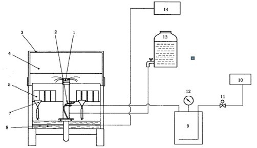
**Description of Key Components:**
1 – Salt-mist dispersion tower
2 – Sprayer
3 – Test box cover
4 – Test box
5 – Sample
6 – Sample holder
7 – Salt mist collector
8 – Wet tank
9 – Air saturator
10 – Air compressor
11 – Solenoid valve
12 – Pressure gauge
13 – Solution tank
14 – Temperature controller
15 – Exhaust gas treatment
16 – Exhaust port
17 – Waste water treatment
18 – Salt tray
19 – Heater
Figure A.1 presents the front view of the salt spray test chamber design, while Figure A.2 illustrates the side view, giving a complete visual understanding of the structure and layout.
After completing the salt spray test, it is essential to properly manage the residual mist and wastewater. The system should be treated in a suitable manner before discharging the mist through the building's exhaust outlet and the wastewater into the designated pipeline. This ensures safety, compliance with environmental regulations, and maintains the integrity of the testing environment. Proper maintenance and handling after the test are crucial for the longevity of the equipment and the accuracy of future tests.
Hyaluronic Acid Injection Filler Foe Face
Hyaluronic Acid Injection Filler Foe Face,Anti-Aging Cross Linked Hyaluronic Acid,Dermal Filler Injection Syringe,Hyaluronic Acid Hyaron Filler
Shijiazhuang Asa Technology Co., Ltd. , https://www.hskinlift.com